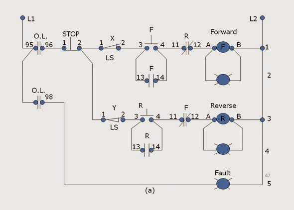

- #Forward and reverse motor control micrologix how to#
- #Forward and reverse motor control micrologix serial#
It is good practice to keep the Enable pin separate so that the sequence is: disable output switch polarity enable output. This is not recommended because the output is always enabled and there could be circumstances when the IC shorts out the +5V motor supply and 0V when it switches the output polarity.
#Forward and reverse motor control micrologix serial#
In some circuits you will see the +5V logic and Enable pins connected together. , DC motor forward and reverse controller, speed control drive board, serial port control, upper computer process.

purple – +5V for motor supply – in this instance, fed from the Pi’s 5V supply, though if you were driving a 12V motor this is where you would connect an external power supply.yellow – 3.3V for the logic level converter.
#Forward and reverse motor control micrologix how to#
For a more precise diagram on exactly how to connect the L293D, please have a look at here. You can find the specification for the L293D IC on the Texas Instruments website. Finally, after defining our functions, we call a quick init(), then ask the forward and reverse functions to run for 0.5 seconds. What these functions are going to do is initiate the proper changes to make the wheels go either forward, or reverse, depending on our goals. The connections between the Pi, breadboard, ICs and motor are shown here. Next, we define our forward and reverse functions. I have tried to avoid the temptation to use forwards and reverse because these words are too prescriptive and the direction of the motor clearly depends on how you have connected it up and how you define true forward and reverse for your application.

00 and 11 both mean stop – no output voltage.These in turn connect through a logic level converter to the inputs of the L293D, which controls the motor. The Raspberry Pi controls the motor by setting the voltage on two of its GPIO output pins. In this project we use one half of the IC to drive a single DC motor. Control stations have switches that operate production equipment, cranes, motors, and other industrial machinery to keep production chains running smoothly and safely. The Texas Instruments L293D dual H-bridge IC has two separate control circuits and can control two conventional DC motors or one stepper motor. In this project we use one half of the IC to drive a single DC motor. This project will show you how to control the rotational direction of a small motor without using any mechanical relays. This project will show you how to control the rotational direction of a small motor without using any mechanical relays.


 0 kommentar(er)
